The ASRock X399 Phantom Gaming 6 Motherboard Review: $250 Sixteen Core Stunner
by Gavin Bonshor on March 12, 2019 10:00 AM EST- Posted in
- Motherboards
- AMD
- ASRock
- ATX
- ThreadRipper
- X399
- TR4
- 2950X
- 2.5G
- Phantom Gaming 6
Visual Inspection
The ASRock X399 Phantom Gaming 6 motherboard represents one of two gaming branded models from its Threadripper product stack, the other being the ASRock Fatal1ty X399 Professional Gaming. The ASRock X399 Phantom Gaming 6 ($250) sets its sights on the cheaper end of the Threadripper market, and sets its sights on the 16-core Threadripper processors segment at a more affordable price point.
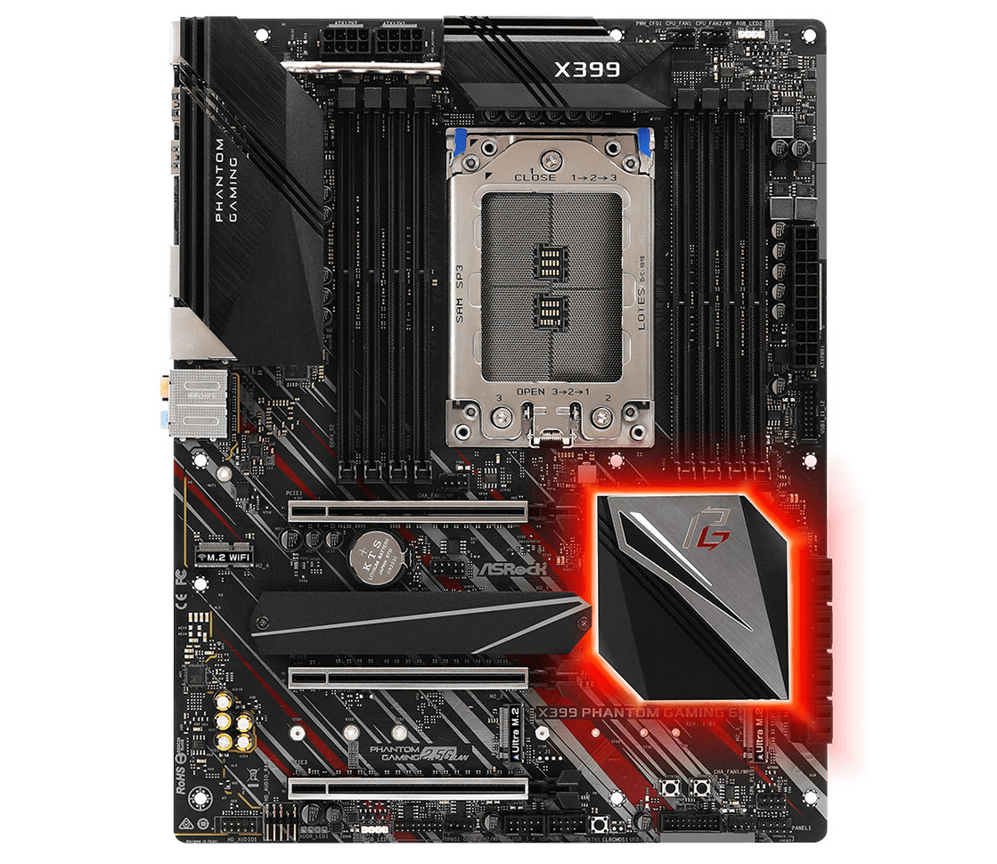
On the design of the X399 Phantom Gaming 6, the overall theme centres around black aluminium heatsinks and a matte black PCB with red and silver accents on the bottom half of the board. The chipset heatsink follows the same accentuation and adds a Phantom Gaming logo on the silver section. Underneath the chipset heatsink is RGB LED lighting which can be controlled via the ASRock Polychrome RGB software or via the BIOS. Users have the option to add their own RGB LED strips with support for two regular RGB 12V headers and a single addressable RGB header; there is support for Razer Chroma products which can be accessed via the software.
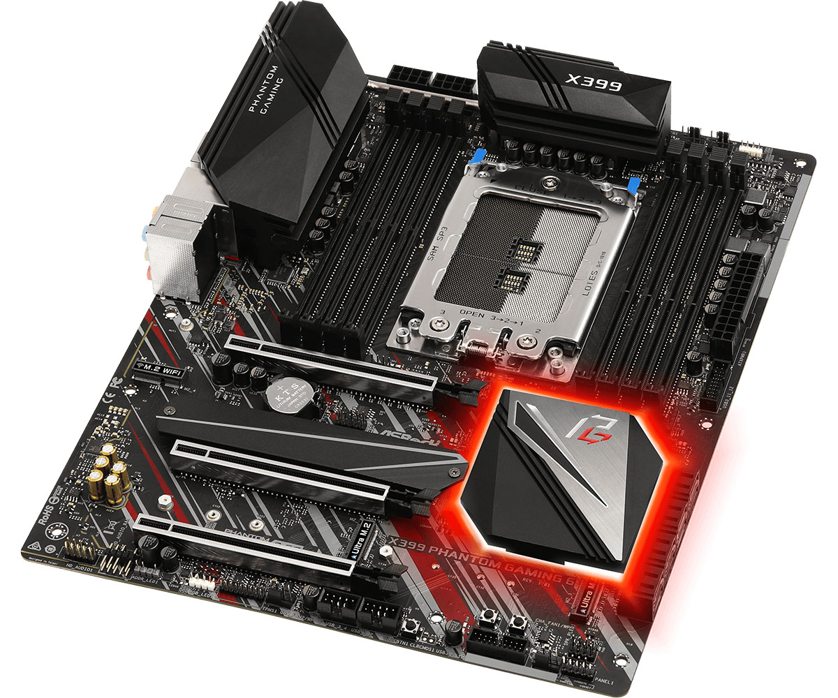
Focusing on the top half of the motherboard, there are two 8-pin 12 V ATX inputs designed to provide the CPU with the required power from the PSU. Flanking either side of the Threadripper TR4 socket is a total of eight memory slots; four on either side. Threadripper processors have support for quad-channel memory and this board specifically supports up to 128 GB of DDR4-3400. Cooling support stretches around the board's edge with a total of five 4-pin headers present. These are divided into three sections; one for the CPU fan, one for a water pump/AIO and three for chassis fans.
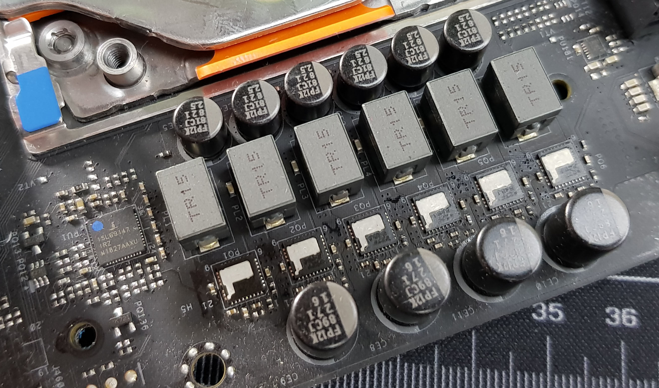
On the power side, the ASRock X399 Phantom Gaming 6 uses a 6+2 configuration with two individual AMD SVI2 PWM controllers. This includes an Intersil ISL69147 PWM controller handling the 6-phase CPU Vcore and an ISL69144 4-phase PWM controller taking care of the 2-phase SoC section. ASRock’s MOSFET of choice is the Intersil ISL99227 power stages rated at 60 A and feature direct metal contacts which make up all the boards eight phases; no doublers in sight on this model. Making up the rest of the power delivery is eight 60 A inductors with one assigned to each power stage and is using Nichion Black 12K capacitors throughout.
| X399 Motherboard CPU Power Delivery (Gavin's Reviews) |
|||||
| Motherboard | Controller | H-Side | L-Side | Chokes | Doubler |
| ASRock X399 Phantom Gaming 6 | ISL69147 6+0 |
6 | 6 | 6 | - |
| ASUS X399 ROG Zenith Extreme |
ASP1405 8+0 |
8 | 8 | 8 |
- |
| MSI MEG X399 Creation | IR35201 8+0 | 16 | 16 | 16 | 8 x IR3599 |
Providing power to the CPU is two 8-pin 12 V ATX CPU power inputs and the X399 Phantom Gaming 6 has support for Threadripper processors up to 180 W TDP. For a chip such as the Threadripper 2950X, the power delivery is very capable for all but the most extreme of overclockers and enthusiasts, users and gamers will find a power setup like this good enough for the boards price point.
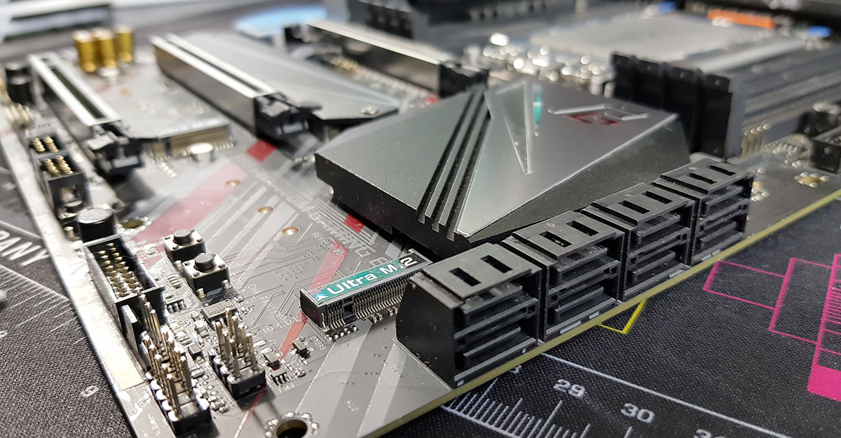
ASRock has implemented three full-length PCIe 3.0 x16 slots which operate all with full bandwidth. Each slot is protected with ASRock Steel Armor and ASRock hasn’t included any PCIe 3.0 x1 slots. The ASRock X399 Phantom Gaming includes three M.2 slots all capable of supporting NVMe SSDs, with the third slot supporting both PCIe 3.0 x4 and SATA drives. On the top slot, up to M.2 22110 drives can be installed while the other two slots located level with each other support up to M.2 2280 drives. At the bottom right-hand corner of the board is eight SATA slots with support for RAID 0, 1 and 10 arrays.
| ASRock X399 Phantom Gaming 6 CPU PCIe Layout | |||
| Number of Installed PCIe Cards on CPU |
PCIe_2 | PCIe_4 | PCIe_5 |
| x1 | x16 | - | - |
| x2 | x16 | x16 | - |
| x3 | x16 | x16 | x16 |
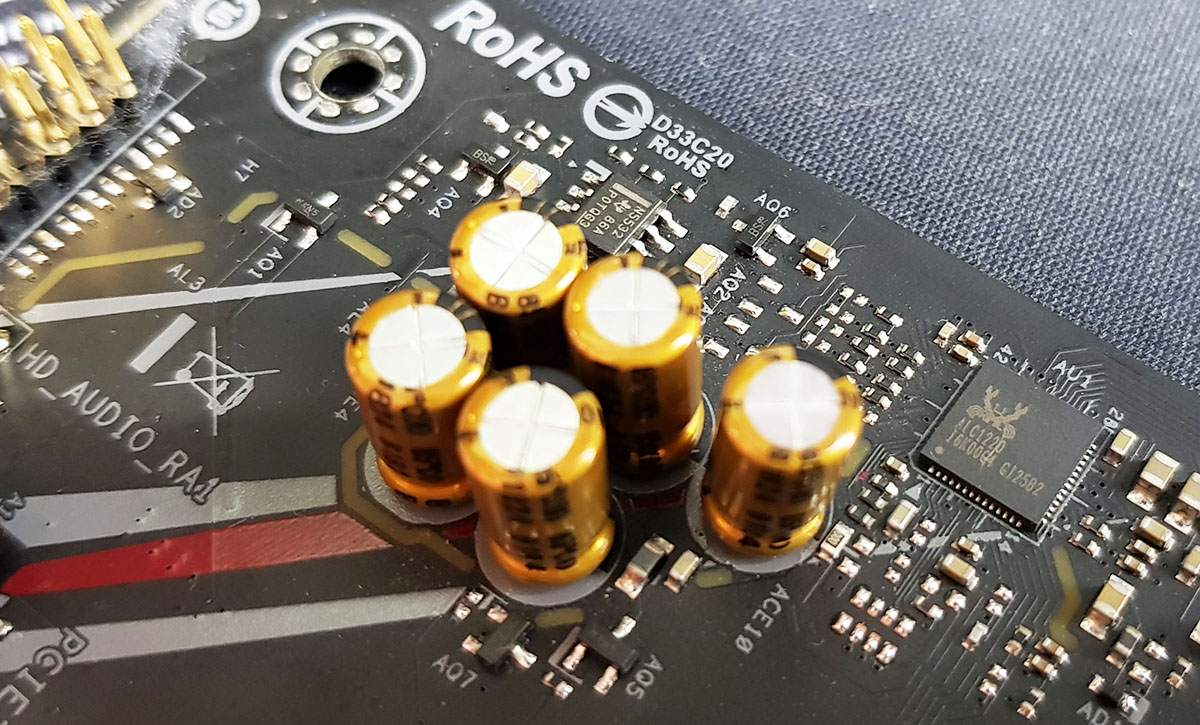
Located at the bottom of the right-hand side of the board is the audio section with a Realtek ALC1220 HD audio codec which is completed with five Japanese Nippon Chemi-Con gold audio capacitors. The audio is separated from the rest of the PCB and includes a front panel audio header with a right-angled connector; the ALC1220 codec doesn’t include an EMI shield. ASRock has also included a Texas Instruments NE5532 header amplifier to bolster the quality of the front panel audio.
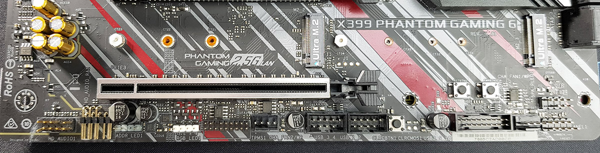
Just to the right of the audio PCB is a variety of headers with one of the RGB 12 V headers and a single addressable RGB 5 V header; the second RGB 12 V header is located at the top right of the board. Also present is a TPM header, two chassis fan headers, two USB 2.0 headers allowing for four ports, one of the two USB 3.1 G1 headers, a clear CMOS button, a reset and power button, as well as front panel connectors for power switches.
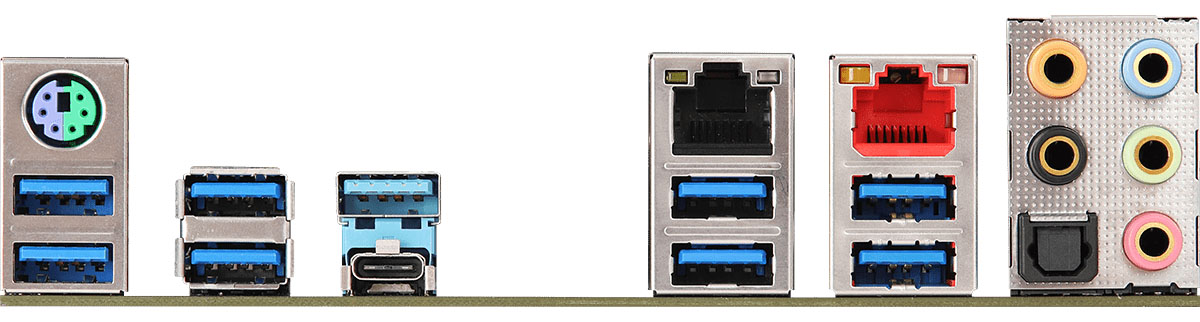
Touching on more of the USB connectivity, the rear panel has just two USB 3.1 G2 ports consisting of a single Type-A and Type-C, with a further eight USB 3.1 G1 Type-A ports. The X399 Phantom Gaming 6 has the capability to host up to eighteen USB ports when the two USB 3.1 G1 and two USB 2.0 (two ports each) headers are factored in coupled with the rear panel ports. Also located on the rear panel is dual RJ-45 LAN consisting of a Realtek Dragon RTL8125AG 2.5 GbE Gaming NIC and an Intel I211-AT 1 GbE controller; the I211-AT has support for PXE. The Realtek ALC1220 audio codec offers five 3.5 mm color coded audio jacks and S/PDIF optical output, as well as a legacy PS/2 keyboard and mouse combo port.
What's in The Box
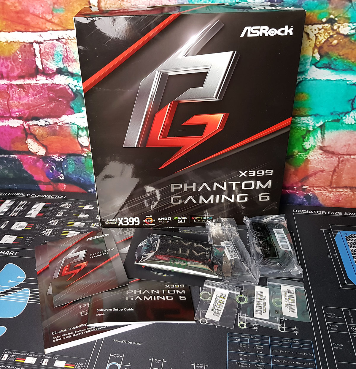
The ASRock X399 Phantom Gaming 6 comes supplied with a basic, yet handy bundle with a quick installation guide, software CD, rear panel IO shield four SATA cables, a two-way SLI HB bridge and four M.2 screws. Also featured is a Wi-Fi bracket for users adding their own Key E M.2 2230 Wi-Fi modules.
- User manual and quick installation guide
- Software setup guide
- Software installation CD
- Four SATA cables (two right-angled, two straight-angled)
- Two-Way SLI HB bridge
- Four M.2 screws
- Rear panel Wi-Fi bracket (M.2 Key E module sold separately)


22 Comments
View All Comments
drajitshnew - Tuesday, March 12, 2019 - link
Thanks for this review, this mobo has some very good design choices. Is there some way the post latency can be improved in THIS board.EliteRetard - Tuesday, March 12, 2019 - link
On a similar note, why is it listed as "Non-UEFI POST Time"? Are you actually disabling UEFI and going with a legacy BIOS for post time? Why, and how does that affect post time? I imagine anybody using this board will want to use UEFI.I am glad that POST time is being measured though, it's an important metric for me and many people I build computers for. Some people might think it unimportant, but when POST vary so drastically the differences are very tangible. Most of the people I build computers for also directly correlate bootup times to the performance of the machine (no matter how many times I try to explain it). I know I still would never accept a MOBO with a 30sec POST time.
GreenReaper - Tuesday, March 12, 2019 - link
They may mean "non-Graphical", but still using UEFI under the hood. It's unlikely to have display acceleration, so it takes extra CPU time to draw fancy pictures (as I found when using graphical console modes on my Linux microserver - 8-bit and 16-bit were proportionately faster than 24-bit).gavbon - Wednesday, March 13, 2019 - link
You can't disable UEFI as UEFI and BIOS are both types of firmware and in themselves, they aren't the same. With the UEFI firmware and CSM, it can emulate or pretend to POST like a non-UEFI BIOS. This is a more consistent way of doing things to show performance across a range of boards etcclose - Thursday, March 14, 2019 - link
But it would help to tell us what the boot time is with "optimized defaults" so to speak. I mean it's great if you can "show performance across a range of boards" but why mention only how long it take is non-UEFI mode for comparison? Why not also in UEFI mode? Is that comparison not useful? Or is the board always in non-UEFI mode?kobblestown - Wednesday, March 13, 2019 - link
Yes, this MB has some good design choices. For the price. I would have preferred to have either a 10G Ethernet adapter or a PCIe2.0x4 slot, e.g. where the heatsinked M.2 slot is (and the battery should be moved somewhere else. In my opinion 10G is taking off (I already have a direct 10G link between my X399 and my server) and will soon be within reach for most consumers. Having to occupy a x16 slot for a 10G adapter sends shivers down my spine. Plus, you could also wish to use a 4x4 bifurcation adapter board to install more nvme SSDs (3 is sometimes not enough) and then you'll be left with a single slot for a GPU.As for the POST times, I hope they can get them down to the other X399 boards. I see no reason why it should be twice longer. I have the Asrock X399 Professional Gaming and POST is already excruciatingly slow. Probably the panoply of PCIe devices is to blame (lspci shows more than 60 devices apart from the user-installed ones!)
Kevin G - Tuesday, March 12, 2019 - link
I think this needs to be edited a bit for clarity on page 1:"The audio PCB is separate from the rest of the PCB"
There is no separate audio PCB from the pictures I see as implied by that statement. I think the intent was to read 'the audio circuitry is separate from the rest of the PCB'.
Kevin G - Tuesday, March 12, 2019 - link
Two more on page 4:"For the start of our Z390 reviews" I think should read "Since the start of our Z390 reviews"
Also...
"Many due to..." I thank you missed a word there. ;)
Ryan Smith - Wednesday, March 13, 2019 - link
Thanks!lmcd - Tuesday, March 12, 2019 - link
*separate PCB layerwhich is in fact true (or at least their marketing claims as much)